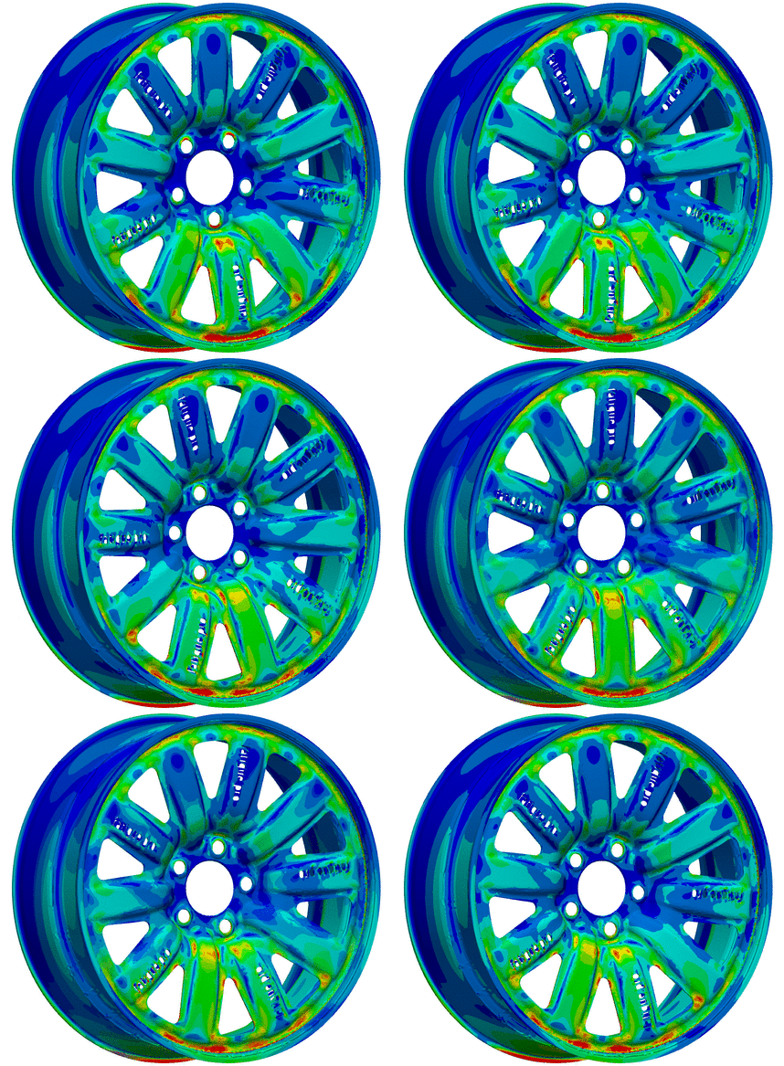
Keep the wheels turning. A steel wheel with shell elements has been on my list for a long time. In the past, I always had only aluminum rims with solid elements in the simulation (see wheelstrength.de). In this post I want to focus on the FEM calculation in PrePoMax.

I made my own steel design and that is inspired by the wheel of the Sono Sion (sonomotors.com media-gallery). I used an existing printable 3D model from thingiverse.com and derived from that a surface geometry in FreeCAD. And I also punched “fatigue.pro” into the disc with FreeCAD.

I prepared a shell mesh and defined a steel material for disc and rim. The disc mesh group is connected with tie contact to the rim.

I defined a vertical load at the shoulder of the rim over a section of 36 degrees. And fixed the wheel at the five bolt holes in the middle.

Now we can submit the calculation with “Run” in Analysis. On my computer it takes lesser than 3 minutes to calculate all six load steps in the CalculiX solver.
Now we can check the results. First of all, always check the deformations.

Next we can take a look on the stress. Make sure that you are looking at the expanded form of the shell elements (see keyword OUTPUT=3D). Otherwise you will not find the bending stress (compare stress inside and outside in next figure).

You can use the “Exploded View” and “Section View” option for a closer look into the contact area between disc and rim.

If you need more possibilities to plot the results or if you like to use ParaView then the CalculiX result file (*.frd) can be converted into the ParaView VTK format (*.vtu). In the PrePoMax Forum you can find the useful tip “Converting results to ParaView format“.

If I am honest, I did not expect such good results and so many possibilities when I use only free available opensource software.
I could also imagine a fatigue calculation in Fatlab or even an additional load case cornering.
Give PrePoMax a try and if you like you can load this example from the steel wheel pmx file (9 MB).

