I would like to calculate the finite element stress of a 5MW wind turbine hub for a fatigue calculation in Fatlab and I came across PrePoMax. PrePoMax is an open-source pre- and postprocessor for an also open-source Finite Element Analysis solver CalculiX.
I would like to explain how a more complex model can be calculated with free and preferably opensource tools. And in this case I want to use the following 3 tools:
- FreeCad – CAD geometry – Create a geometry and export as step file
- PrePoMax – FEM calculation – Import geometry, preprocessing and FE stress calculation
- Fatlab – Fatigue calculation – Import model & FE stress and calculate damage utilization
In this post I like to explain the second point “PrePoMax – FEM calculation”. If you like you can check it out yourself in PrePoMax with this reduced wind turbine hub pmx file (44 MB).

If you need some tutorials for the basic usage of PrePoMax then you can check this video tutorial or the PrePoMax manual.
Geometry
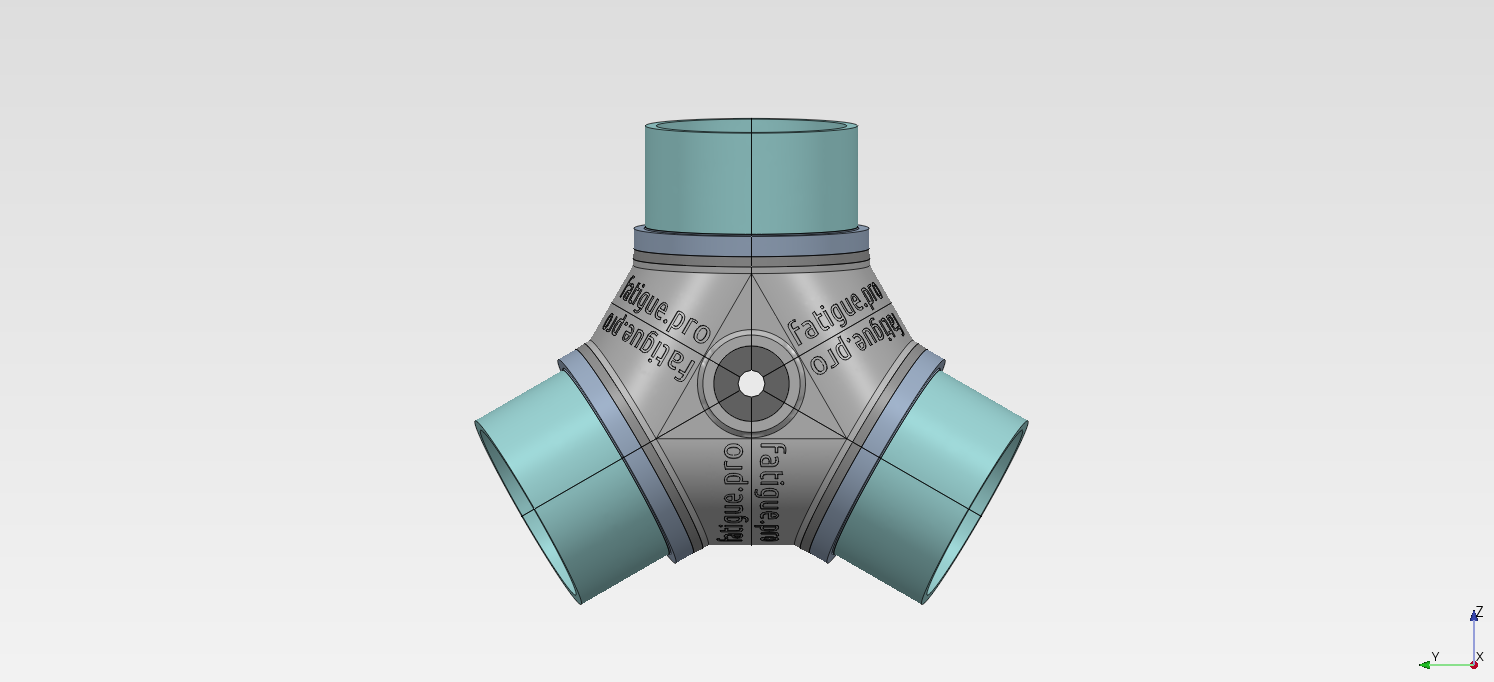
Because of the lack of a geometry modeller we need a geometry. I prepared a simplified wind turbine hub geometry in FreeCAD and exported that as a STEP-file.

And I added some simple geometry for pitch bearing, blade and main shaft to provide a more realistic stiffness for the FE stress calculation.

After we create a new model and select the needed system units we can import the geometry in PrePoMax. To create meshes over more than one solid you have to create compound parts.

Next step is meshing. I used some coarse “Meshing Parameters” and create a Tetrahedron mesh with 1.4 million nodes and 810054 elements. If this is not fine enough, then the mesh can easily be refined or you can continue detail analysis with sub-models (video tutorial).
If you get a successfully created mesh then you can proceed in the FE Model part.

FE Model
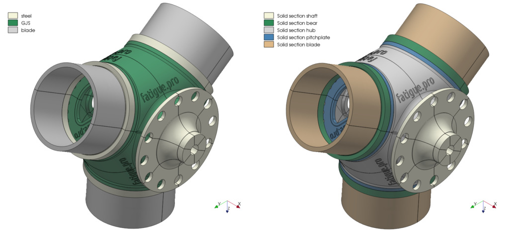
In this section you have to define materials and element sections according your model. Hub and pitch-plate are spheroidal graphite cast iron like “EN-GJS-400-18-LT”, pitch bearing and main shaft are heat-treated alloy steel like “42CrMo4”. Blade dummy are assumed as fibreglass reinforced epoxy composite with Young’s modulus of 25000 MPa and a Poisson’s ratio of 0.3. And then you have to define “element” sections with the corresponding element type (solid section) and material.
From the load calculation we need the point position of the blade root load. In my case it is in the middle of the pitch bearing flange and we need a remote structure to connect these virtual simulated point to the realistic structure. In PrePoMax we can use the “Rigid body” option in “Constraints” to create a remote force / moment on a “Reference point” (also called remote point). You can find more information about that approach in a video tutorial from FEAnalyst.

The mesh of one compound part is not connected to another compound part, because of the independent meshes of the previous combined compound parts. So we need a kind of bonded contact between the different compound parts. In PrePoMax we can sew meshes together with the “Tie” constraint. With “Search Contact Pairs tool” we can automatically create the tie constraints between all compound parts in a very easy way.

And now we are ready to create the first analysis step. We have to add boundary conditions “BCs” like the fixation at the main shaft in the main bearing area and we have to add “Loads” at the defined “Reference points” at the blades.

For the following result plots I defined 6 load steps to simulate a rotation of 120° under conditions with high load. I selected a load condition with maximum My load from a load simulation and generated a synthetic load to simulate a hub rotation. It is derived from the time series V12 in the 5MW Wind turbine hub Fatlab example (WTG_hub.zip).

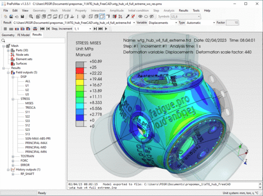
Now we can submit the calculation with “Run” in Analysis. On my computer it takes lesser than 10 minutes to calculate all six load cases in the CalculiX solver.

And after a successful run we can jump with “Results” directly into the post-processing.
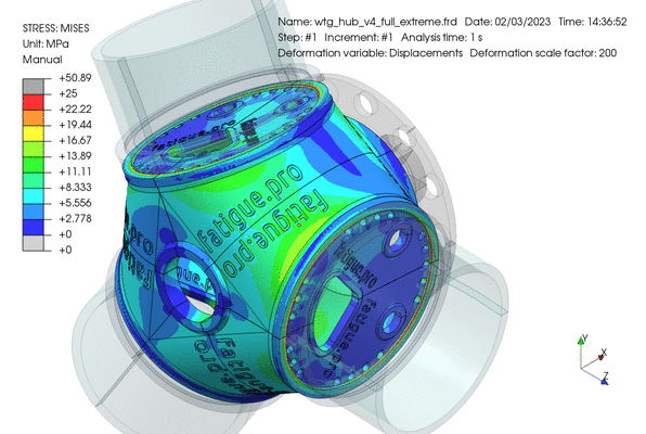
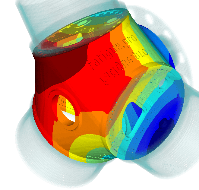
Results
We can create a lot of different plots and animations in the “Results” section in PrePoMax.
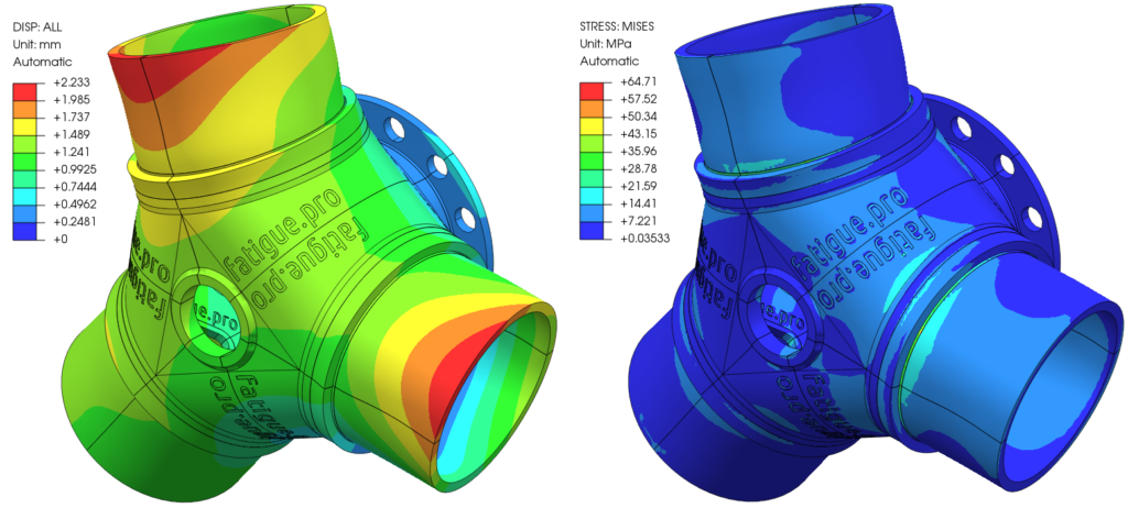
Next plot shows the animated deformation of the hub for all 6 defined load steps, that shows a hub rotation from 0° up to 120°.

And there are many possibilities to present the results in an eye-catching way.

If you need more possibilities to plot the results or if you like to use ParaView then the CalculiX result file (*.frd) can be converted into the ParaView VTK format (*.vtu *.vtk). In the PrePoMax Forum you can find the useful tip “Converting results to ParaView format“.

Update 19 September 2023: I remade this wind turbine hub model in Ansys Mechanical with a full Hexaeder mesh (Hex20 & Wedge15 only) and made some comparison of the results (see Wind turbine hub calculation in Ansys). So I also came back to these calculation results and I prepared a new animation with the CalculiX graphical interface (CalculiX GraphiX: cgx). Following animation are the same deformation results than in the figure “Deformation animated from step 1 to step 6 (120°)“, but I found no way to rotate the model around the X axis with precise angle values in PrePoMax.

Update 21 November 2023: Now I also translated the Ansys Mechanical full Hexaeder mesh (Hex20 & Wedge15 only) with Gmsh into PrePoMax (see Wind turbine hub also rotates in Calculix). The results are looking unbelievable close. You might think that I also imported the result plots from the Ansys calculation, but the PrePoMax results are calculated with Calculix.
All this tools are freely available and opensource. Give PrePoMax a try and you can load this example from the reduced wind turbine hub pmx file (44 MB).