Some month ago I prepared a geometry from a rest of a bicycle chain in FreeCAD. I used only a caliper to measure the dimensions. Because I really wanted to test the nonlinear contact in PrePoMax with my own model.
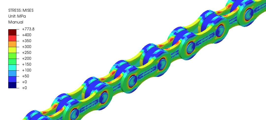
I would like to focus here on the results in PrePoMax and Fatlab. Because I was already a bit impressed how easy it was to calculate and how good results could be achieved. Next figure shows no crazy stress and it was not needed to deselect elements with crazy results.

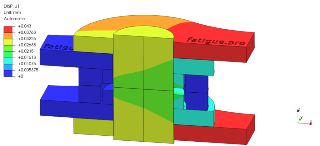
But now i will try to explain the used contacts a bit. In the next figure you can see the displacements with true scale. The inner link is fixed on the left and shows not much displacements (blue colors). The pin in the middle moves a bit because of a air gap between inner link and pin (green to yellow). That is made as a frictional contact with µ = 0.01 because of lubrication and it allows rotation around the pin. The pin is connected to the outer link with a press fit (modeled in the geometry offset as measured). So this contact pair moves together and that is assumed as normal steel to steel frictional contact with µ = 0.1 (yellow to red). The roller between the inner links is more or less force free and works in that tension load case only as a spacer (blue).
I used “linear contact” and because of the very low contact penetration (COPEN) I reduced the contact stiffness to only two times the Elastic modulus. For more information about useful contact settings in Calculix I can recommend this YouTube video.
Next figure shows the mesh with some refinements at the contact areas. Such fine mesh was not really needed, you can get also good results with a coarser mesh.

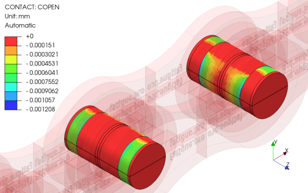
Now we can take a closer look at the contact results. I always check the contact penetration (COPEN), because if the values are too large then the contact stiffness must be increased. The press fit contact of the pin to the outer link is over an angle of more than 180° and very smooth. The contact to the inner link is over an angle of around 150° and this angle will change with the load level.
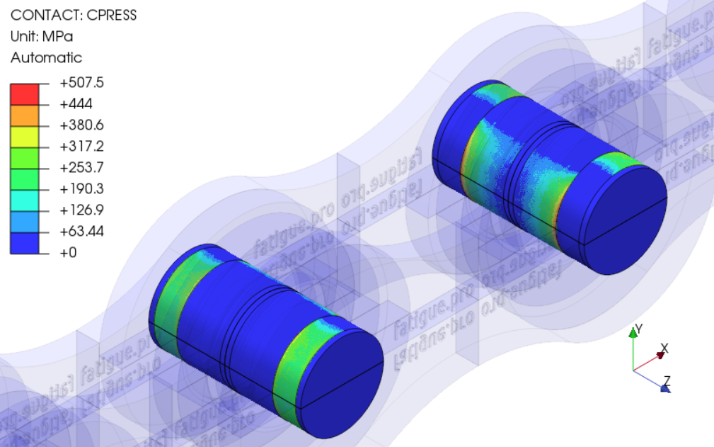
Next figure shows the contact pressure (CPRESS) and we see only high values on the edge of the inner link.
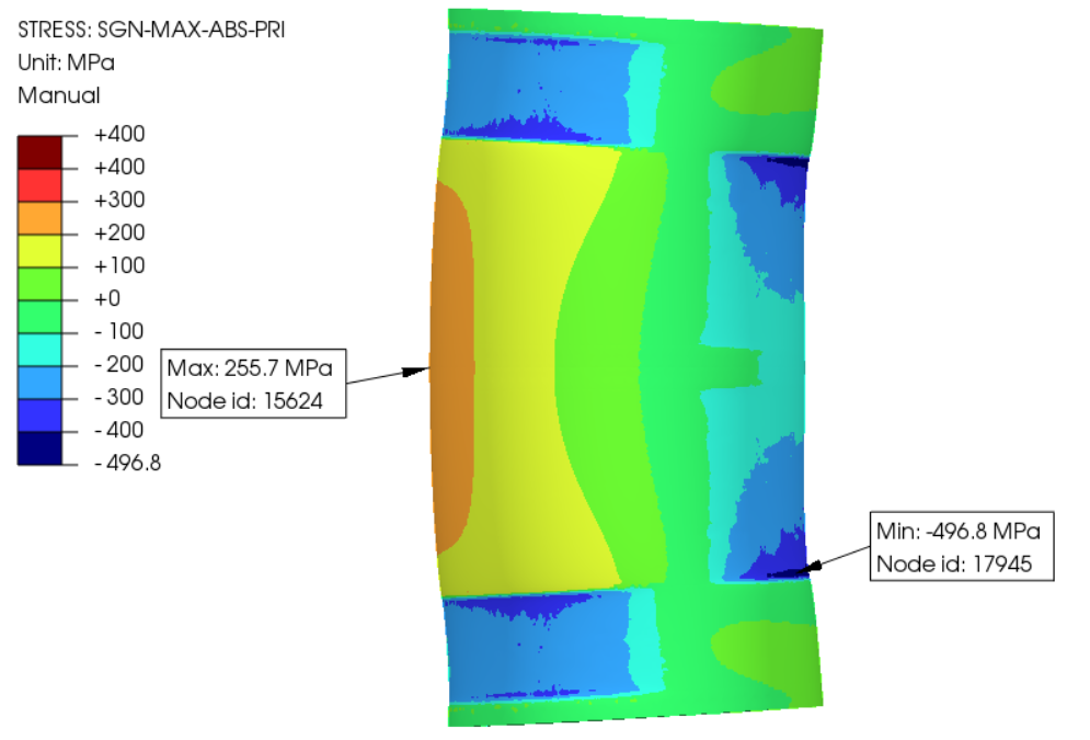
So let us check the stress in the pin and the signed maximum absolute principle stress corresponds very well with the contact pressure. But the pin has mostly compression stress and looks not critical.
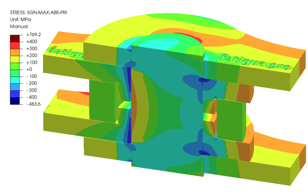
In the half model is a clear compression area between the inner and outer link (light blue). But it shows also high tension stress.
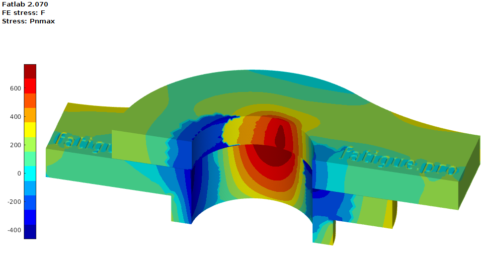
The highest absolute stress is in the tension area of the inner link. According the figures above is this area not in contact. So it is pure tension at the hole edge and we can already expect 3 times higher stress than the Membrane stress (see example with a hole in a “endless” plate).

Therefore, I imported the chain links from the Calculix frd result file into Fatlab to perform a fatigue analysis (see more details with a wind turbine hub example).
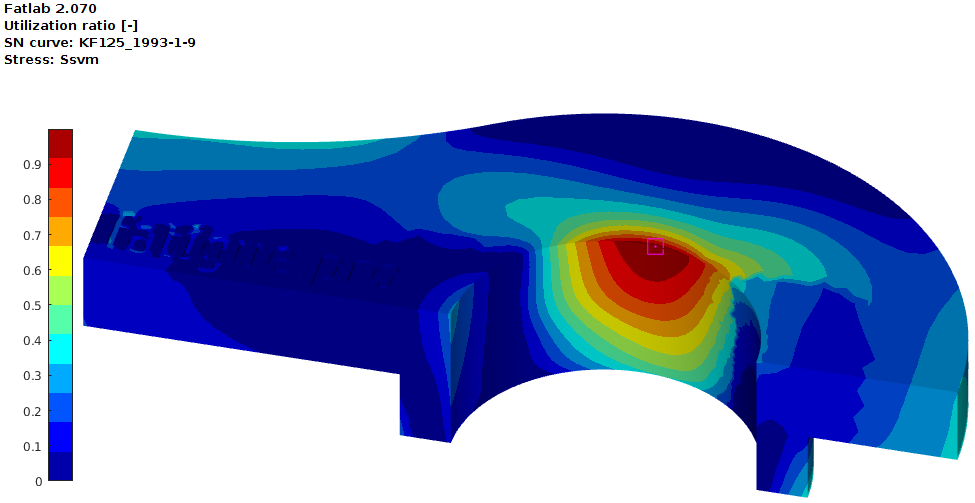
With a S-N curve acc. DIN EN 1993-1-9 and a variable load we can setup a fatigue calculation in Fatlab.

We used only one tension load case and so we find the highest fatigue utilization at the same position as the maximum absolute stress. In areas with compression is the fatigue utilization significant lower because of the used mean stress correction. The selected “60% compression” removes 40% of the compression stress from the stress range, but that helps only in areas with compression stress.
If the stress results are as good as from PrePoMax then results from the contact area can be easily used for fatigue calculations. This was a very nice example of nonlinear contact in PrePoMax (try it out, it is free and opensource) and another test for the Calculix results interface in Fatlab.

